QuenchPod logoQuenchPod™
OverviewModelsSystemSpecPricingPrototypeDemoDeckFilingContact

QuenchPod™ investor deck

8 / 27 · The concept in the field

Current slide

Visualisations

The concept in the field

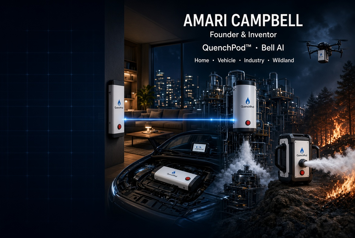
How a QuenchPod is placed, fitted and delivered — concept imagery, not photographs of tested hardware.

Amari Campbell QuenchPod concept artwork
Home, vehicle, industry and wildland
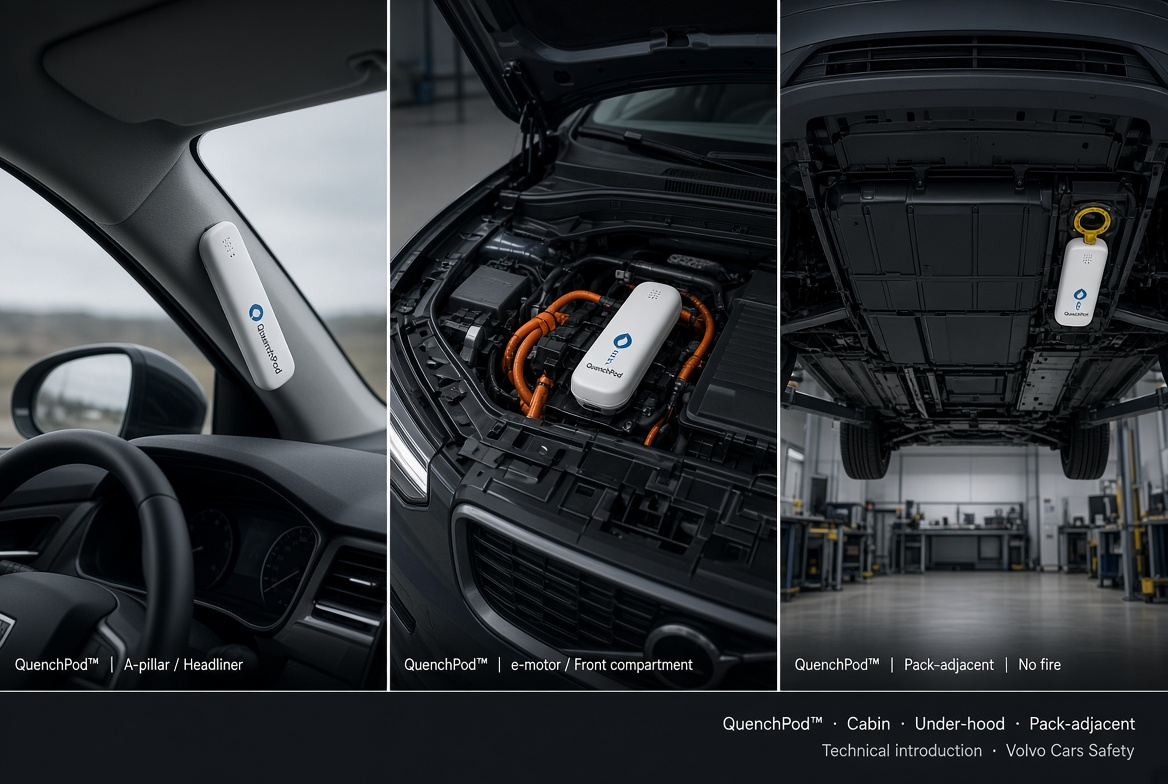
QuenchPod vehicle installation artwork
Cabin, front compartment and pack-adjacent
QuenchPod™ — Concept-stage technology8 / 27
Elapsed00:00:00

Next

QuenchPod™ High-Risk Installation System

One central tank system. Every zone addressed on its own.

Two separately stored suppressant components, kept isolated in standby. On an authorised release they are brought together under controlled flow, aerated into fire-suppression foam and routed through a manifold to the selected zone only — for warehouses, factories, data centres, parking, infrastructure and wildfire-exposed estates.
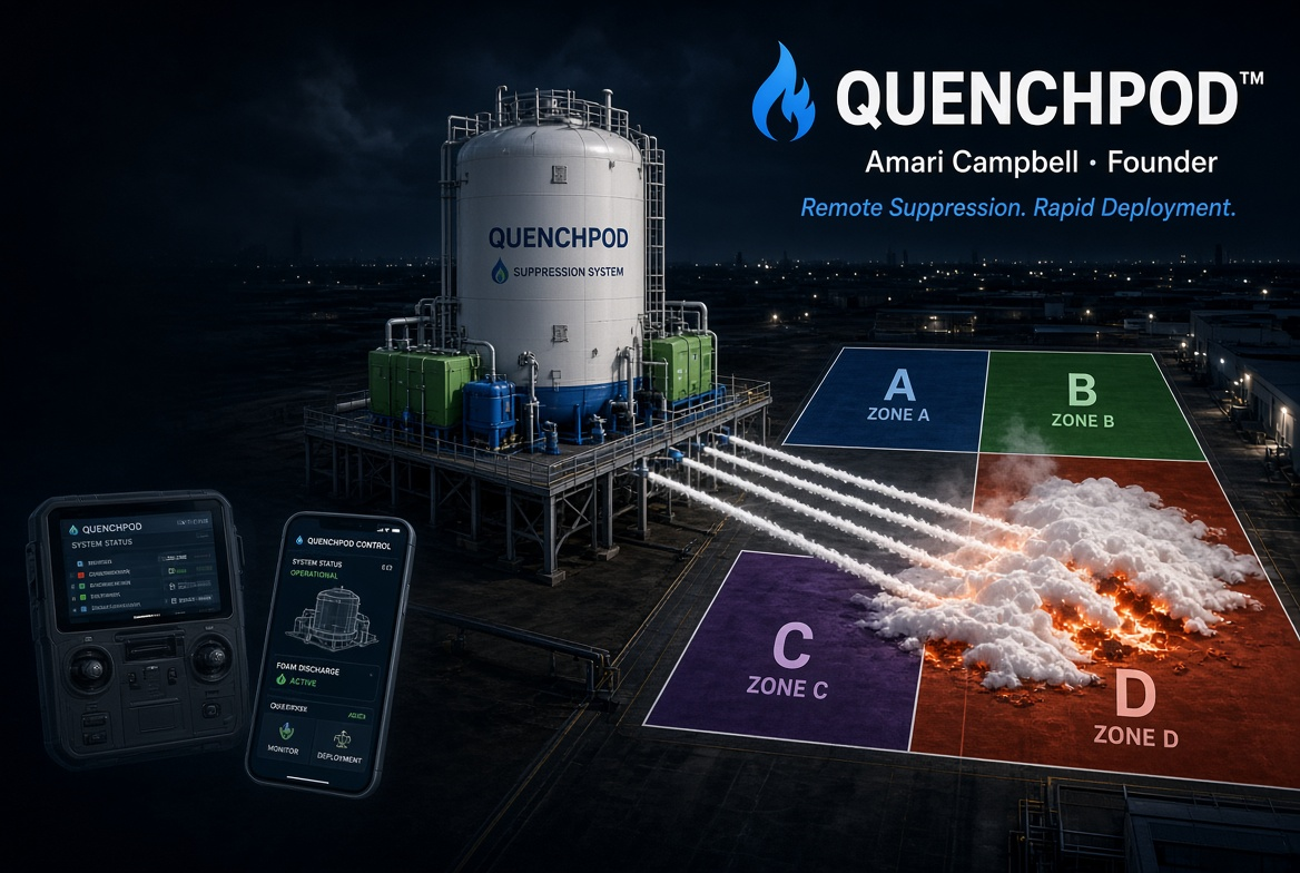
QuenchPod central tank and remote controls showing discharge into Zone D only
Central tank and selective zone discharge · concept artwork
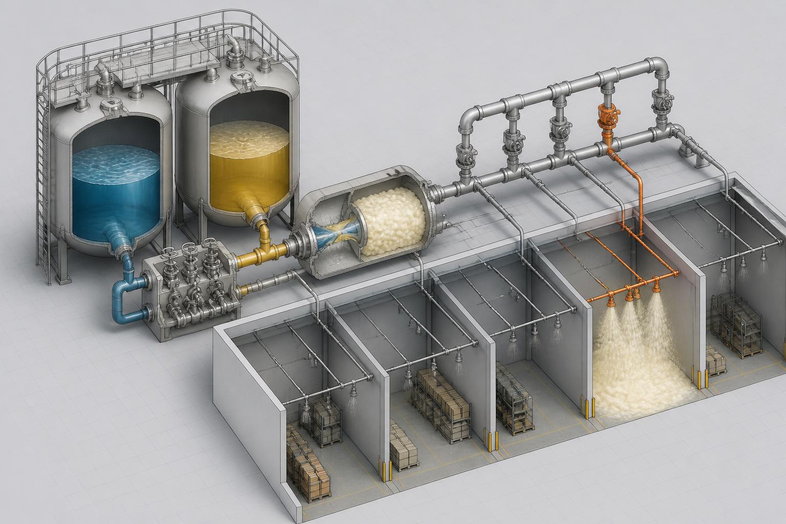
Cutaway showing controlled mixing and zoned distribution
Foam generation feeding zoned nodes
QuenchPod™ — Concept-stage technology9 / 27

Speaker notes

  • These are concept visualisations, not photographs of manufactured or tested units.
  • They show the same platform moving between installed, crew-placed and aerial use cases.
8 / 27 — The concept in the field
QuenchPod logo

QuenchPod™

Remote suppression. Rapid deployment. Safer firefighting.

Concept enquiries

Amari Campbell

amaricam86@gmail.com+353 85 168 7167

Concept-stage technology. Performance and applications subject to engineering, testing, regulatory review and certification.