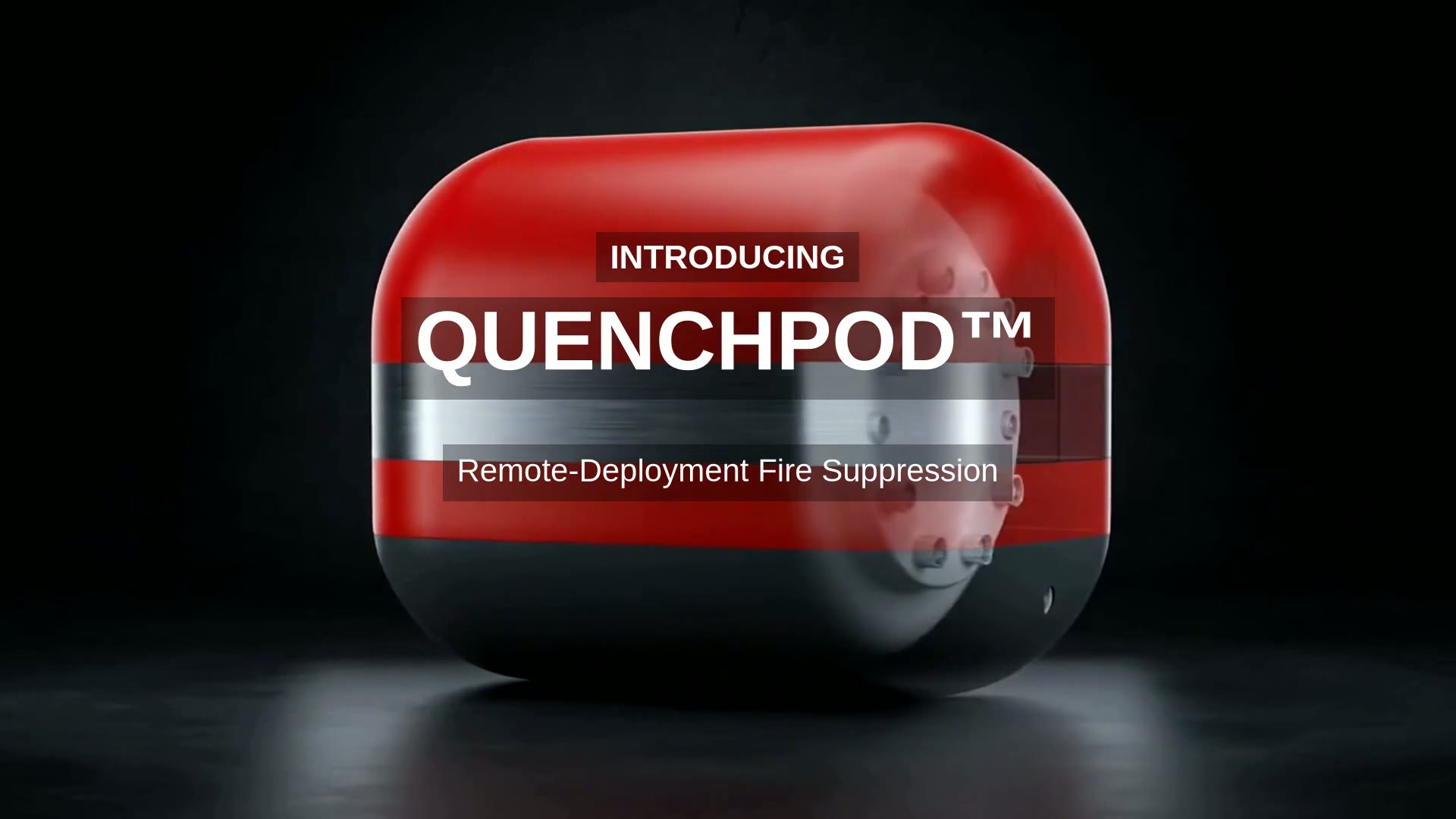

QuenchPod™ High-Risk Installation System
One central tank system. Every zone addressed on its own.
Remote Suppression. Rapid Deployment. Safer Firefighting.
“Get the extinguisher to the fire instead of bringing the firefighter to the fire.”
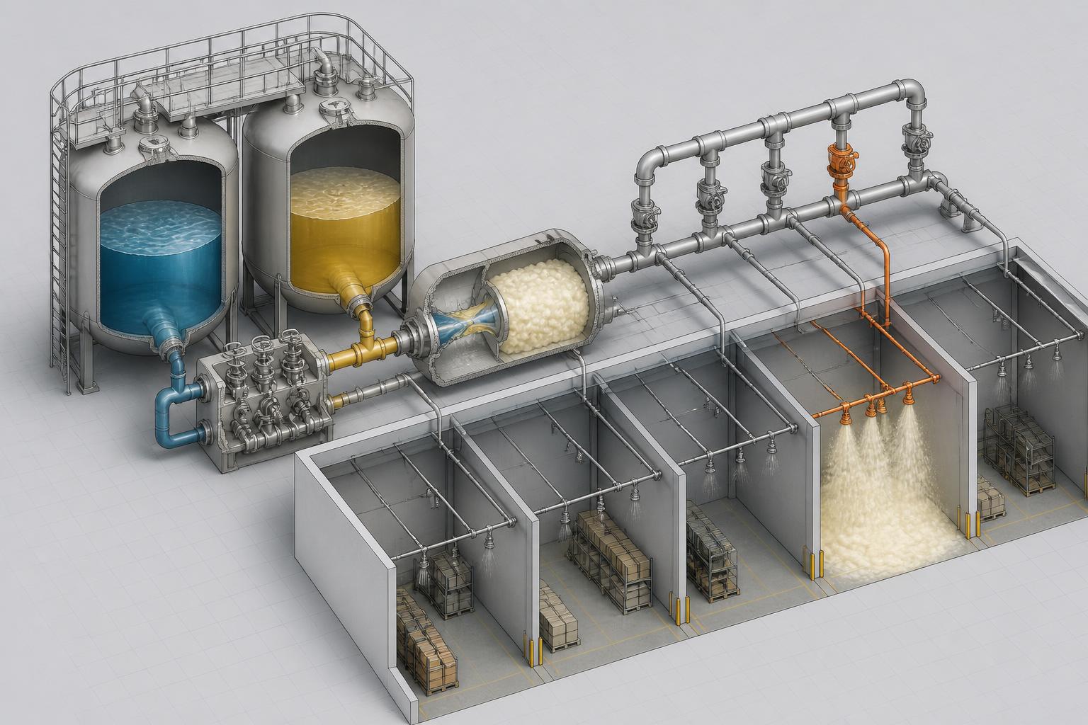
Concept-stage system architecture. Nothing shown here has been built, pressure-tested or certified. Component A and Component B are two separately stored suppressant components supplied by a certified formulation partner; no chemistry, mixing ratio, pressure or reaction parameter is published. Capacities, zone counts and node spacing are design intents to be fixed by a fire engineer against the protected risk.
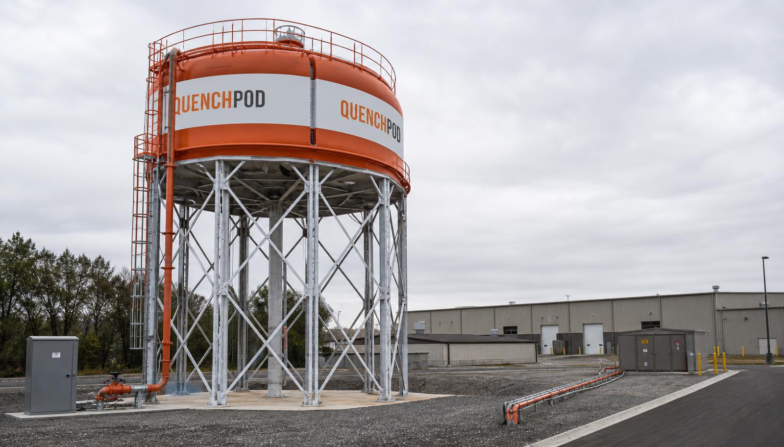
The installation
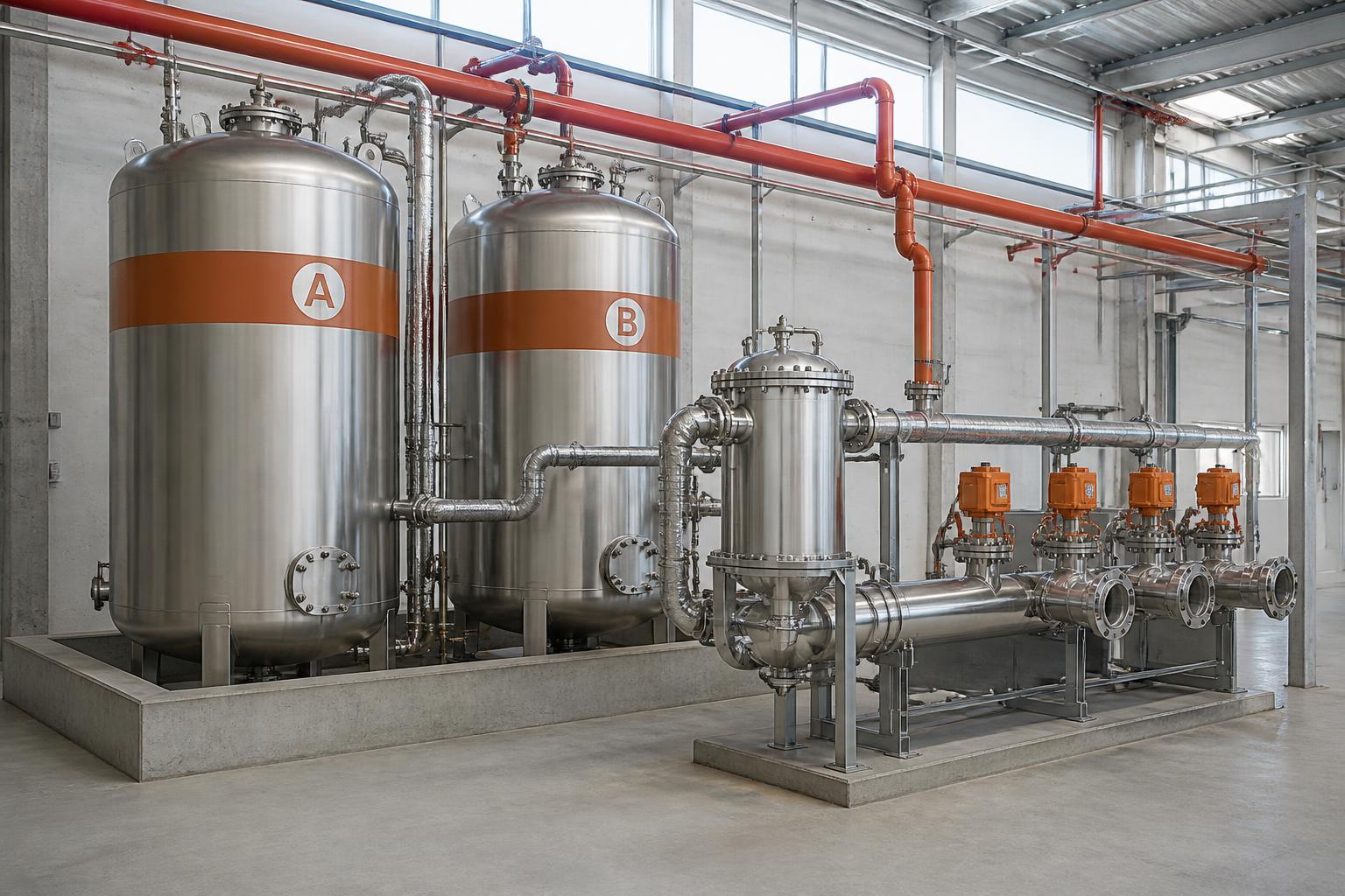
A permanently or semi-permanently mounted tank set, installed like commercial fire-protection plant: two bulk component tanks in a bunded plinth, a mixing and foam-generation assembly and a manifold carrying one valved line per zone into the building.
How the system works
Component A Tank + Component B Tank → Controlled Activation → Mixing / Foam Generation Chamber → Distribution Manifold → Individually Controlled Fire Zones → Foam Discharge. Zone D is shown in alarm: it discharges alone while Zones A, B and C remain charged.
Labelled subsystems
01 · Bulk tank
Component A Storage
Vertical tank holding the first suppressant component, level- and condition-monitored, with fill and sampling points at ground level.
02 · Bulk tank
Component B Storage
Second tank holding the companion component. Same monitoring, separate containment bund, separate fill point.
03 · Normal operation
Isolation System
Double isolation keeps the two components physically apart at all times in standby. Nothing meets, nothing flows, until an authorised activation opens the path.
04 · Authorised release
Activation Control
The control cabinet accepts a verified command — from the detection interface or an authorised Clicker™ — and releases only the selected zone path.
05 · Metered contact
Controlled Mixing Chamber
The two components are brought together under controlled, metered flow. A steady fluid process, monitored end to end — no charge, no pyrotechnic, no shock event.
06 · Expansion
Foam Generation Chamber
The combined stream is aerated into a rapidly expanding fire-suppression foam, generated on demand at the volume the selected zone requires.
07 · Routing
Distribution Manifold
A single manifold carries one independently valved line per zone, so generated foam is routed only where it is needed.
08 · Selective discharge
Zone Control
Each zone valve is addressed individually. A fire in one zone discharges that zone; the rest of the site stays charged and protected.
09 · Discharge point
QuenchPod Node™
Fixed discharge nodes positioned across the property — over racking, plant, charging bays, transformer rooms, roof lines — piped back to the central tank system.
Two ways in, one authorisation
Fire Detection Interface
Wired to the site's detection and alarm system. A confirmed detection in a zone identifies that zone to the control cabinet and raises it to alarm.
Remote Activation
An authorised QuenchPod Clicker™ lets an operator standing at a safe distance select a single zone and release it with a deliberate two-stage action.
System Monitoring
Continuous supervision of tank levels, isolation state, valve position, node integrity and every activation — time-stamped and reportable.
Protected zones
Each zone is a separately valved circuit with its own QuenchPod Nodes™. Selective release means a single incident never costs the whole site its protection.
Zone A
Racking and bulk storage
6 Nodes™
Zone B
Production / plant floor
5 Nodes™
Zone C
EV and battery charging bay
4 Nodes™
Zone D
Switchroom and infrastructure
3 Nodes™
Built for
- · Warehousing and logistics
- · Factories and process plant
- · Data centres and switchrooms
- · Multi-storey and underground parking
- · Energy and transport infrastructure
- · Wildfire-exposed properties and estates
One ecosystem, five formats
One principle across every format: get the agent to the fire, keep the person away from it, and never release more than the situation needs. The same activation logic, the same Clicker™, the same addressable Network™ — whether the agent arrives in a thrown capsule or through fixed pipework.
Portable QuenchPod
Hand-placed or thrown into an early-stage fire.
Installed self-contained QuenchPod
A single pre-mounted unit standing by over a fixed risk.
Drone-deployed QuenchPod
Carried and released where no one can safely stand.
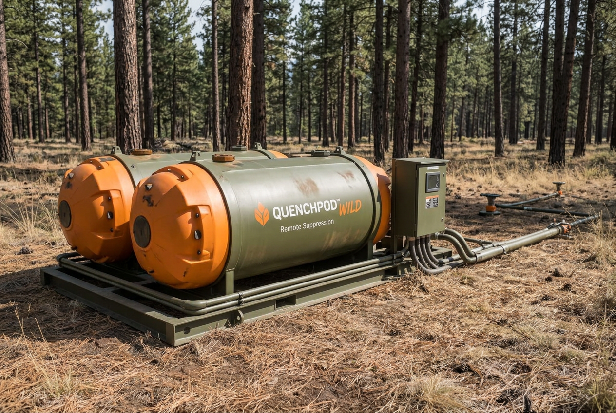
QuenchPod Wild™
Terrain units placed ahead of a fire front.
High-Risk Installation System
Central twin-component tank system feeding zoned nodes across a whole property.